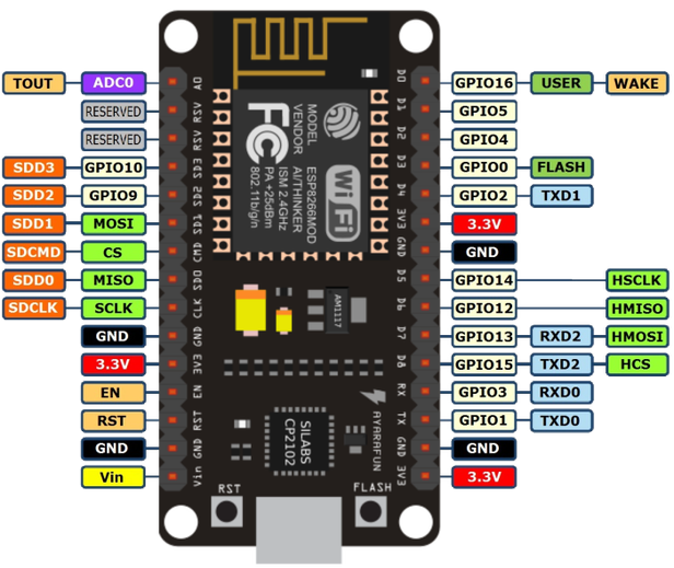
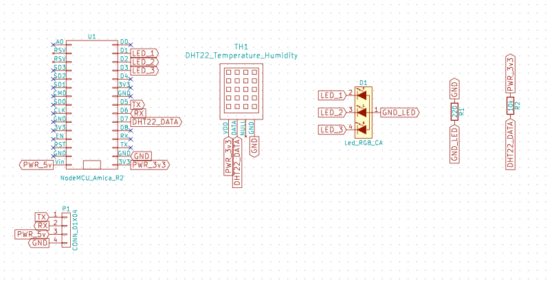
3. PIN Options
3.1. Pins
If you have connected pins differently from the original schema provided in the documentation, make sure you update pin setting from defaults.

3.2. PIN NodeMCU mapping
To do that you do something like this. Let's say you want to move pins for RGB led. You need to overwrite only pins that have been changed from the original layout.
#include "Air.h"

Air air;

// runs once
void setup()
{
  //DHT22 data pin
  //air.pin.dht = D1;

  //RGB data pin
  air.pin.red   = D2;
  air.pin.green = D3;
  air.pin.blue  = D4;

 	//PM Sensor serial data pins
  //air.pin.pmRX = D7;
  //air.pin.pmTX = D8;

  air.setup();
}

// runs over and over again
void loop()
{
  air.loop();
}
3.3. PINs Arduino GPIOx mapping
Alternatively, you can specify numbers of the pins using Arduino GPIO mapping - note recommended
Weird NodeMCU to Arduino mapping
Be aware that NodeMCU pin IDs are not mapping directly to the Arduino GPIO numbers - convert them by using a map provided on the end of the page.
Say you moved PINS like this:

Pins would be reflected like this:
#include "Air.h"

Air air;

// runs once
void setup()
{
  air.pin.dht   = 13;

  air.pin.red   = 5;
  air.pin.green = 4;
  air.pin.blue  = 0;

  air.pin.pmRX  = 14;
  air.pin.pmTX  = 12;

  air.setup();
}

// runs over and over again
void loop()
{
  air.loop();
}
3.4. NodeMCU to Arduino mapping
NodeMCU Pin IDs are not mapping directly to Arduino GPIO numbers - convert them by using map bellow:
| NodeMCU Pin ID | Arduino GPIO | Note |
|---|---|---|
| D0 | 16 | |
| D1 | 5 | I2C Bus SCL (clock) |
| D2 | 4 | I2C Bus SDA (data) |
| D3 | 0 | |
| D4 | 2 | Same as "LED_BUILTIN", but inverted logic |
| D5 | 14 | SPI Bus SCK (clock) |
| D6 | 12 | SPI Bus MISO |
| D7 | 13 | SPI Bus MOSI |
| D8 | 15 | SPI Bus SS (CS) |
| D9 | 3 | RX0 (Serial console) |
| D10 | 1 | TX0 (Serial console) |
Updated almost 6 years ago
