3. DHT22 Temperature and Humidity Sensor
Next, we will connect DHT22, a basic, low-cost digital temperature and humidity sensor which uses a capacitive humidity sensor and a thermistor to measure the surrounding air.
3.1. Connecting it to breadboard

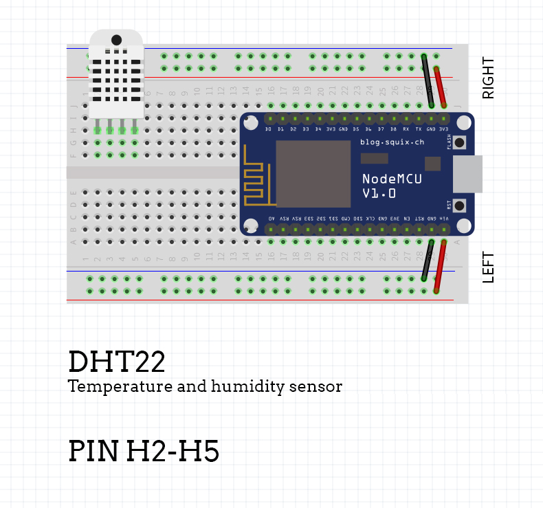
Connect the sensor as shown in the picture above. Use pins H2 to H5.
3.2. Powering DHT22

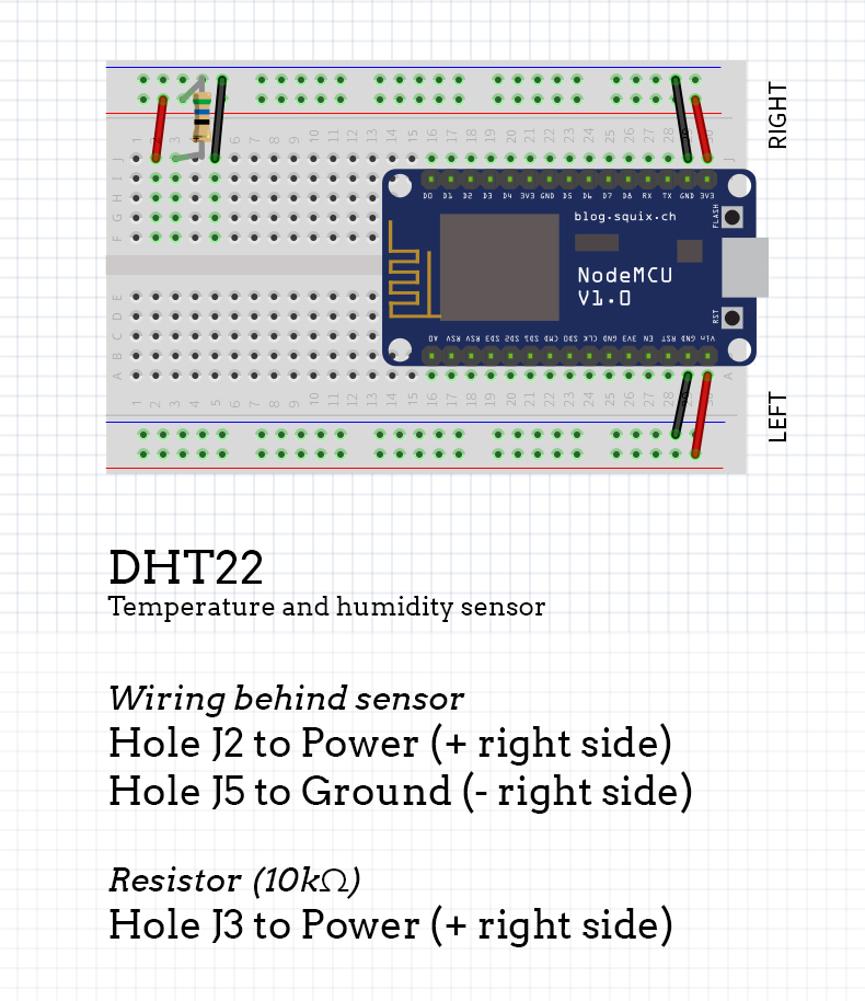
Once you have your DHT22 sensor placed on the breadboard, you will also need it powered up and grounded. To do this, use custom, handmade jumper wires previously made on holes J2 and J5 respectively.
Connect hole J2 to Power (column marked with +sign on the right side), and hole J5 to Ground (column marked with a - sign on the right side).
The next thing you can use is a resistor. In our case, we need a 10kΩ resistor for the DHT22 sensor.
Place it as shown on the picture (holes J3 to Power).
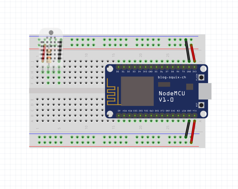
You will notice there is no DHT22 sensor on the image above. That is because of the easier understanding (you can see on the image below both DHT22 and wiring underneath it).

Sensor and wires overlayed for better understanding.
3.3. Connecting it to NodeMCU

You are almost done with your second component, hold tight!
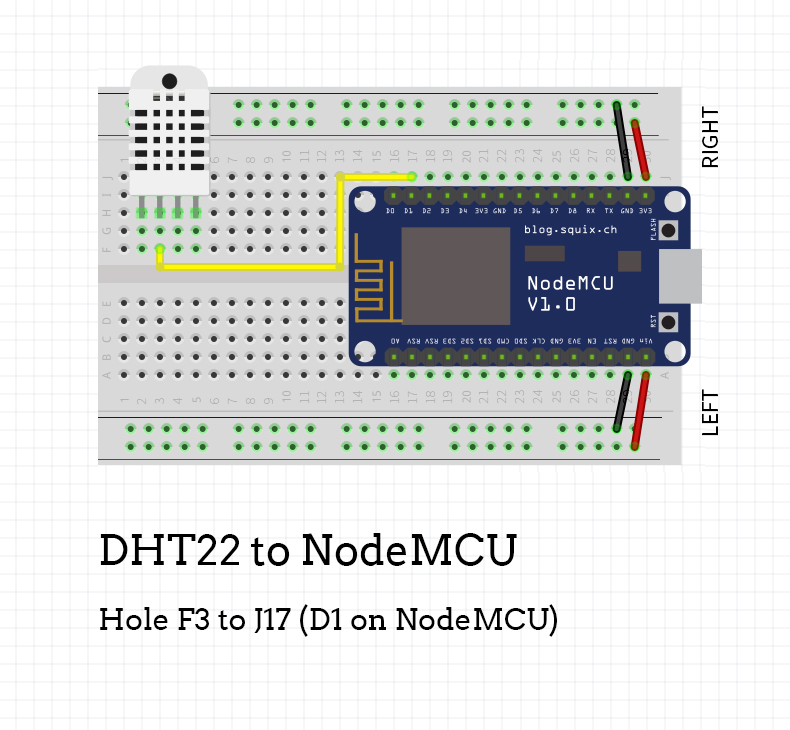
Use a jumper cable to connect it with NodeMCU by using pins noted in the picture above (pin F3 to J17 (pin D1 on NodeMCU).
This cable is used for sending data of the sensor readings to the NodeMCU.
Updated almost 6 years ago
