1. RGB LED Ring
For our first component, we will use LED Ring.
First, you will need to solder three wires to the bottom of the ring.
Solder red wire on the pin that reads VCC (5V power), black wire on the GND pin (ground) and orange wire on IN pin (data in).*
- You can use any wire color you have available instead of orange.
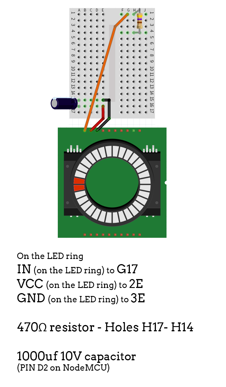
1.1. Connect LED ring with the breadboard (NodeMCU is hidden)

After soldering the wires, connect them as shown on the diagram.
You will also need a 470Ω resistor, as well as a 1000uf 10V capacitor.
Place the capacitor so that the side with (-) mark goes into the ground on the breadboard, and make sure it matches the D2 pin on the NodeMCU above.
You may want to do this as the last step, because of the lack of space.
Updated almost 6 years ago
What’s Next
