3. Prototyping Breadboard
3.1. Description
Breadboards are one of the basic and most fundamental pieces of building circuits and prototyping your devices.
An important thing to know is that when we are talking about 'breadboards' we are actually referring to a solderless breadboard (and not the type of wooden board you make sandwiches on).
What does it mean? It means that, when you want something quickly made (or you are just testing/learning and making a prototype), there is no need to use a soldering iron, you just
plug each component in the right place (if you are following a tutorial of course) and it works!
They are also great for the testing of each component before soldering them permanently. Imagine if you wanted to test a bunch of sensors to see if they work properly, and you had to solder each one and then detach them after. That would take a lot of time, right? Enter breadboards, where you easily rewire and test each one.

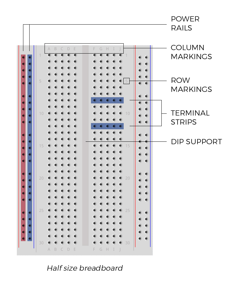
Simple diagram showing each part of the breadboard.
3.2. How it works?
The easiest way to explain this is to open a breadboard and take a look inside.

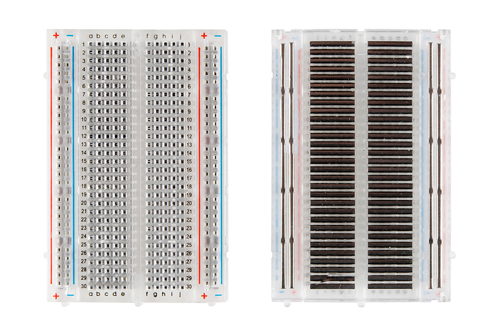
Here we have a half sized breadboard with back adhesive removed to show what's inside.
3.2.1. Terminal strips
The first thing you may notice are a bunch of horizontal rows on the right picture.
These are bottoms of metal clips that allow you to stick a wire or a leg of a component into the exposed holes on top of the breadboard. The clip part then holds it in place.
Metal clip removed from the breadboard.
Once inserted, that component will be connected to anything else placed inside of that same row (metal rows are conductive and they allow current flow from any point in that strip).
There are only 5 holes for each metal clip, meaning that you can have up to five components connected in one particular section, even though there are 10 holes in a single row. We will later explain why that is, but for now, just know that each side of the row is disconnected from the other.
3.2.2. Power rails
Aside from horizontal rows, some breadboards (like the one you are going to use in the first part of the tutorial) have power rails that run vertically along the sides.
These are metal strips identical to the horizontal ones, except that they are usually connected all the way through. They give you easy access to power wherever you need it in your circuit. In this example, they are labeled with '+' and '-' signs and have colored stripes (indicating positive and negative sides).
3.3.3. DIP support
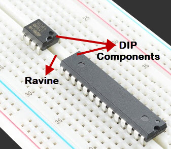
Earlier, we mentioned that each side of the horizontal rows is disconnected one from the other. This small ravine running along the middle of the breadboard is called DIP support.
Why DIP? Many integrated circuits (IC) are manufactured as to perfectly fit onto breadboards. In order to minimize the space they take up, they come in what is known as a Dual In-line Package (DIP).
These chips have legs that fit perfectly over that small ravine, and since each leg is unique, they need to be disconnected from each other.

3.2.4. Row and column markings
Markings on breadboard do not serve any purpose other than helping you manage and organize everything when building your device.
To follow these tutorials, you will need to correctly place each wire or leg in the right place, and these markings will help you to easily manage and find the right hole on the breadboard.
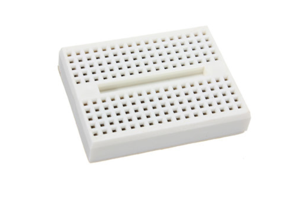
Small prototyping board
In our compact version we will use a small prototyping board, as shown in the picture below:

Mini Solderless Prototype Breadboard
3.3. Where to buy?
| eBay | Breadboard: https://ebay.to/36xHnL0 |
| eBay | Mini breadboard: https://ebay.to/2ZVEAJ5 |
Updated about 6 years ago
