Custom Wiring
Learn how to make your own custom wires that will later be used in hardware setup.
1. Crimping
For our compact version later on (in which we are not using PM adaptor), you will need to prepare a couple of wires beforehand.
This process is called crimping. It is a process in which you use different electrical connectors in order to join two wires together. For our needs, we will use crimp pins, both female and male. In this part of the tutorial, you will learn how to use and manipulate both of them.
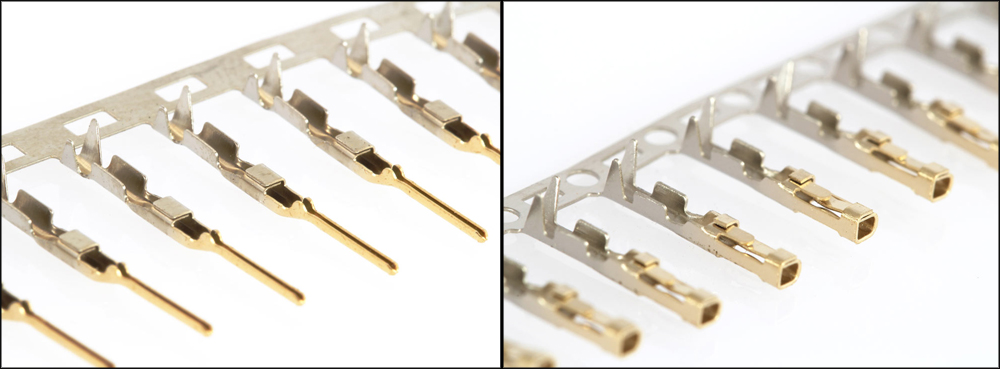
Male (left) and female (right) crimp pins.
1.1. Prepare your tools
In order to do this properly, you will need certain tools.
A decent pair of crimping pliers, a wire stripper and a pair of side-cutters will do the trick.
A scalpel comes in very handy too.

Crimping pliers (left), wire stripper (center) and side-cutters (right).
1.2. Exposing wires
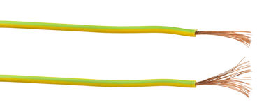
Next, you will want to expose wires. This is done by using wire strippers and carefully cutting insulation (usually around 4-5mm in length from the end you want to connect) and then pulling and peeling it off the wire. This way you get an exposed wire ready for crimping.
1.3. Placing the exposed wire in crimp pin
After removing insulation from the wire, you will want to carefully place it inside of the crimp pin. If you haven't peeled enough of the insulation from the wire so that the exposed part fits nicely inside of the crimp pin, make sure to repeat the previous step.


Exposed wire (brown) being placed inside of the crimp pin.
1.4. Using crimper tool
Next, grab your crimping pliers. These are specifically made for crimp pins and make this step a breeze. You just place them in the right 'tooth' of the pliers and gently press down.
If you don't happen to have crimping pliers around, you can use regular pliers as well. In this case, you will have to manually bend each part of the crimp pin so that it firmly holds the exposed wire in place.
1.5. Using insulation tape/heat-shrink tube
After you have successfully crimped the wires inside crimp pins, you will now add a couple of layers of insulation tape around it. This way you get extra protection and even firmer hold.
The best thing to use is a heat-shrink tube if you can get your hands on one (place the tube around the wire and use a lighter to heat it and it will shrink!), but don't worry if you can't, insulation tape will work just as fine.
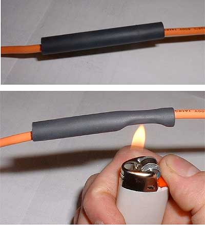
Heating of heat-shrink tubes. Notice how it wraps around the wire once heated.
2. Jumper wires
In order to make your breadboard less crowded and make it look more elegant, you will at times want to use jumper wires instead of jumper cables. What is the difference you wonder? Take a look at the picture below.
Pins on breadboard connected using smaller jumper wires.
Ok, now that you know what is it we are talking about, you might wonder how to get/create them?
You could always go and buy yourself a set of these wires that have already been made to fit most of the breadboards out there, but what happens when they don't quite fit? Not to worry, because making your own is a breeze.
2.1. Prepare your tools
As in the process above, you will want to use wire-strippers and side-cutters (no crimping pliers needed for this one). Also, you will need a solid core conductor (wires).
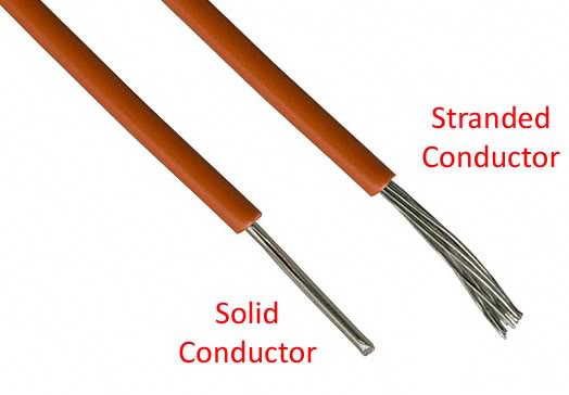
Solid conductors are easier to manipulate with and will be much easier to place inside of the breadboard pins.
2.2. Measure the distance
The next thing you will need to do is measure the distance between the two pins you want to connect. Use any old ruler or whatever you can get your hands on.
When you have measured the distance, use the side-cutter pliers to cut the wire. Make sure to leave extra 5mm (a bit more just to be on the safe side) on both sides of the wire.
2.3. Expose the wires
After cutting your wires to different lengths, you will now want to expose the ends. Use a wire-stripper tool to do this most effectively (you can use side-cutters or even simple scissors, just make sure not to cut the wire in half).
Wires should look something like the ones in the picture below.
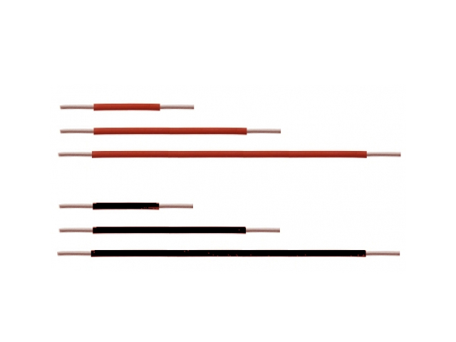
Different lenghts of solid core wires (conductors).
2.4. Bend the wires to fit
After exposing the wires, the last thing left to do is simply to bend them in a U-shape form so they can safely fit the breadboard pins.
3. What does success look like?
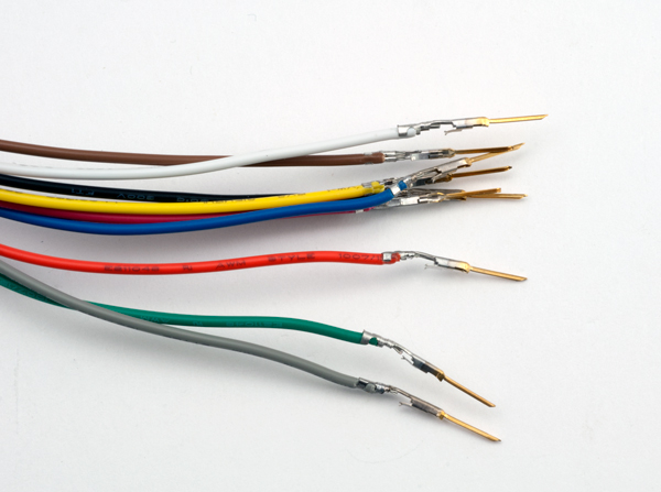
Crimping part. Pictured are male pins successfully crimped.
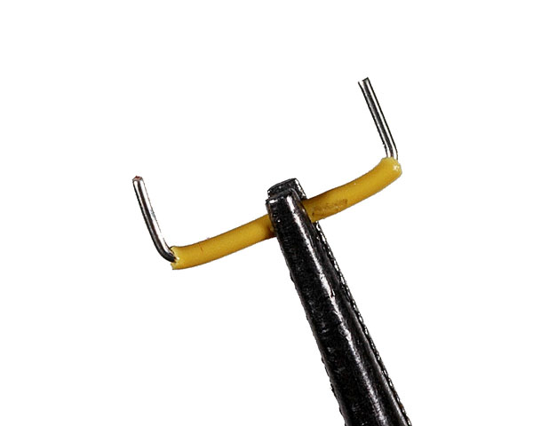
Small jumper wire. Formed in a U-shape to fit breadboard pins.
Updated almost 6 years ago
