1. NodeMCU
In the first part of the hardware setup, you will learn how to connect and power your NodeMCU development kit.
1.1. Connecting it to breadboard

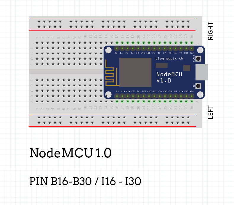
In order to connect NodeMCU to the breadboard, you will want to place it as shown in the picture above. You will use up pins B16 to B30 on one side, and pins I16 to I30 on another side of the breadboard.
Columns that are left free (column A and column J) will later be used to connect other components to NodeMCU.
1.2. Powering NodeMCU

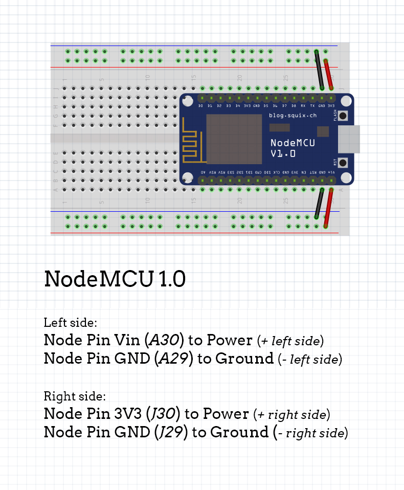
In order to power the breadboard and its components, we will want to connect NodeMCU to power and ground strips by using jumper cables.
Connect the first pin on NodeMCU (one that says 3V3) to a power strip on the right side (column marked with + sign). Do the same thing with the second pin (right next to it that says GND) to a ground strip on the right side (column marked with a - sign).
Also, connect the first pin on the other side (one that says Vin) to a power strip on the left side (column marked with + sign), and the pin next to it (GND again) to the ground strip on the left side (column marked with - sign).
1.3. What does success look like?
Option with standard DuPont jumper cables.
Updated almost 6 years ago
