4. RGB LED
4.1. Connecting it to breadboard

For the last component, we will connect RGB LED.
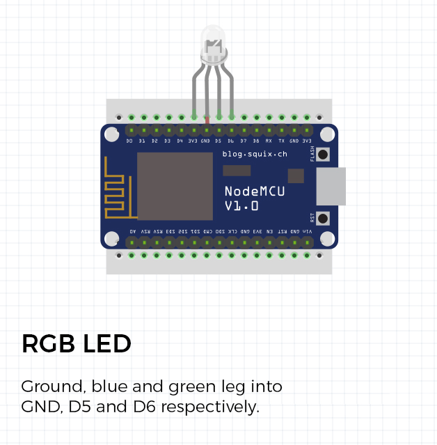
Place it as shown on the picture, but make sure that the far left (red leg) is not connected to the breadboard.
The second leg from the left, ground, goes into GND pin. Next one, blue leg, goes to D5 and the last leg (guessed it, green), goes to D6.
4.2. Connecting resistor to LED

Same as we did in the first tutorial, we need to add a resistor to our light. Since there is no free space, we must do this outside of the breadboard.
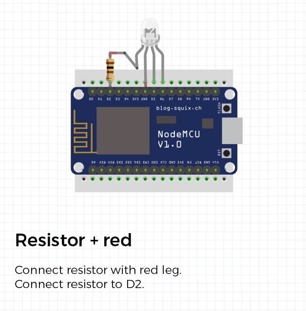
Get your 100Ω and connect it to the red leg of your LED light. You can do this anyway you like, just make sure that they are touching each other at one point. After wrapping it around the leg, use a soldering iron and solder them together.
4.3. Connecting resistor to breadboard
After you have connected LED with the resistor, connect the remaining resistor leg to D2 pin on your breadboard.
Updated about 6 years ago
