2. RGB LED Ring
The second step is where we introduce the new component, RGB LED ring.
In order to get it working, you will first need to solder three wires to the bottom of the ring.
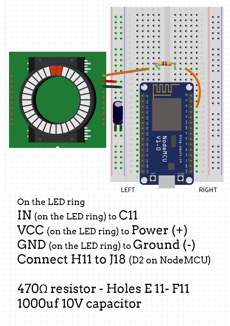
Solder red wire on the pin that reads VCC (5V power), black wire on the GND pin (ground) and orange wire on IN pin (data in).

After soldering the wires, connect them as shown on the diagram.
You will also need a 470Ω resistor, as well as a 1000uf 10V capacitor.
After placing a resistor in the right spot, use a regular wire to connect everything with the NodeMCU (in our case, it is an orange wire going from hole H10 to J18 on the breadboard).
Place the capacitor so that the side with (-) mark goes into the ground on the breadboard.
Updated almost 6 years ago
What’s Next
