4. PM Sensor - PMS1003
Last but certainly not least, PM sensor as our main component for measuring particle matters in the surrounding air.
PM sensor is represented as a regular IC in this step.
4.1. Connecting PM sensor to breadboard
After you have gone through wiring tutorial, you will need to implement your newly acquired knowledge and create male pins from the cable that comes along with the PM sensor.
PM cables
PM sensor comes along with 8 cables.
Create male pins on:
- Green (RX)
- Blue (TX)
- Orange (GND)
- Purple (5V)
You can cut off or fold:
- Red
- Black
- Yellow
- White
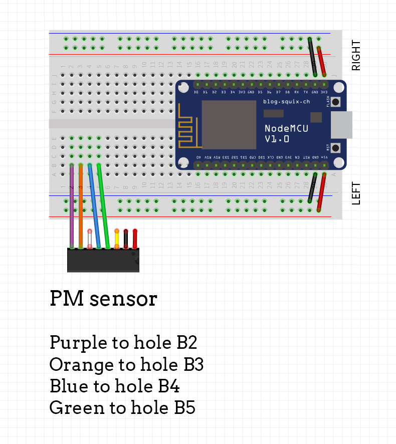
Once done, connect the new wire pins with the breadboard as shown in the picture.
Purple wire to B2, orange to B3, blue to B4 and green to B5.

4.2. Connecting PM sensor to power and ground
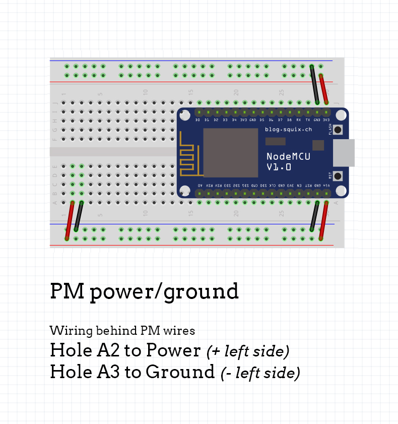
Now, we will need to power it up. Use small jumper wires (also previously made by following wiring tutorial) and connect them as shown below.

4.3. Connecting PM sensor to NodeMCU
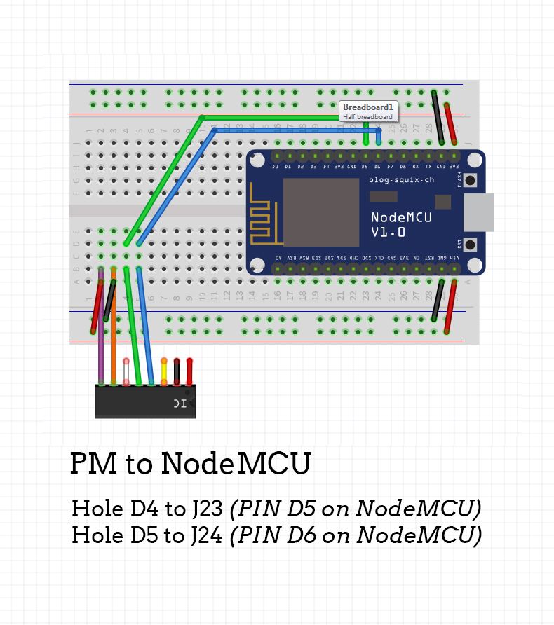
One thing left to do is to connect everything to NodeMCU. We do this by connecting holes D4 and D5 to pins J23 and J24 (D5 and D6 on NodeMCU).

Uncomment the lines below:
air.debug.errors   = true;
air.debug.readings = true;
air.debug.led      = true;
air.debug.json     = true;
Updated almost 6 years ago
