2. PM Sensor - PMS1003
2.1. Custom wiring
As in the previous version with only one LED light, the first thing you need to do is create male pins out of your PM sensor cables. Do that by following steps in this custom wiring tutorial in case you still haven't.
2.2. Cutting off certain wires
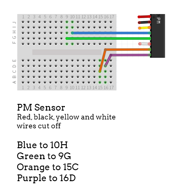
Next, we want to cut off 4 wires from PM sensor that are of no use for us anymore.
Starting from the red one, remove the following wires:
Red (1), black (2), yellow (3), white (6).
Tie them up so you don't get confused later on.
2.3. Create male pins
Out of the four remaining wires (green (4), blue (5), orange (7) and purple (8)) you need to make custom pins. Get your tools and follow the wiring tutorial. Remember, you want to make male crimp pins.
Once you are done, you should have 4 wire pins that can easily be placed in their corresponding place.
2.4. Connecting to NodeMCU
After you have your wires ready, the last thing you need to do is to connect each pin as shown in the picture below.
The green wire goes to pin D5, blue wire to D6, while orange and purple wires go to GND and Vin pins on the other side of the breadboard.

Updated almost 6 years ago
