3. BME280 Temperature, Humidity and Pressure Sensor

Next, we will connect BME280, an environmental sensor with temperature, barometric pressure, and humidity. This sensor is great for all sorts of weather and environmental sensing and uses I2C communication protocol.
3.1. Connecting it to breadboard

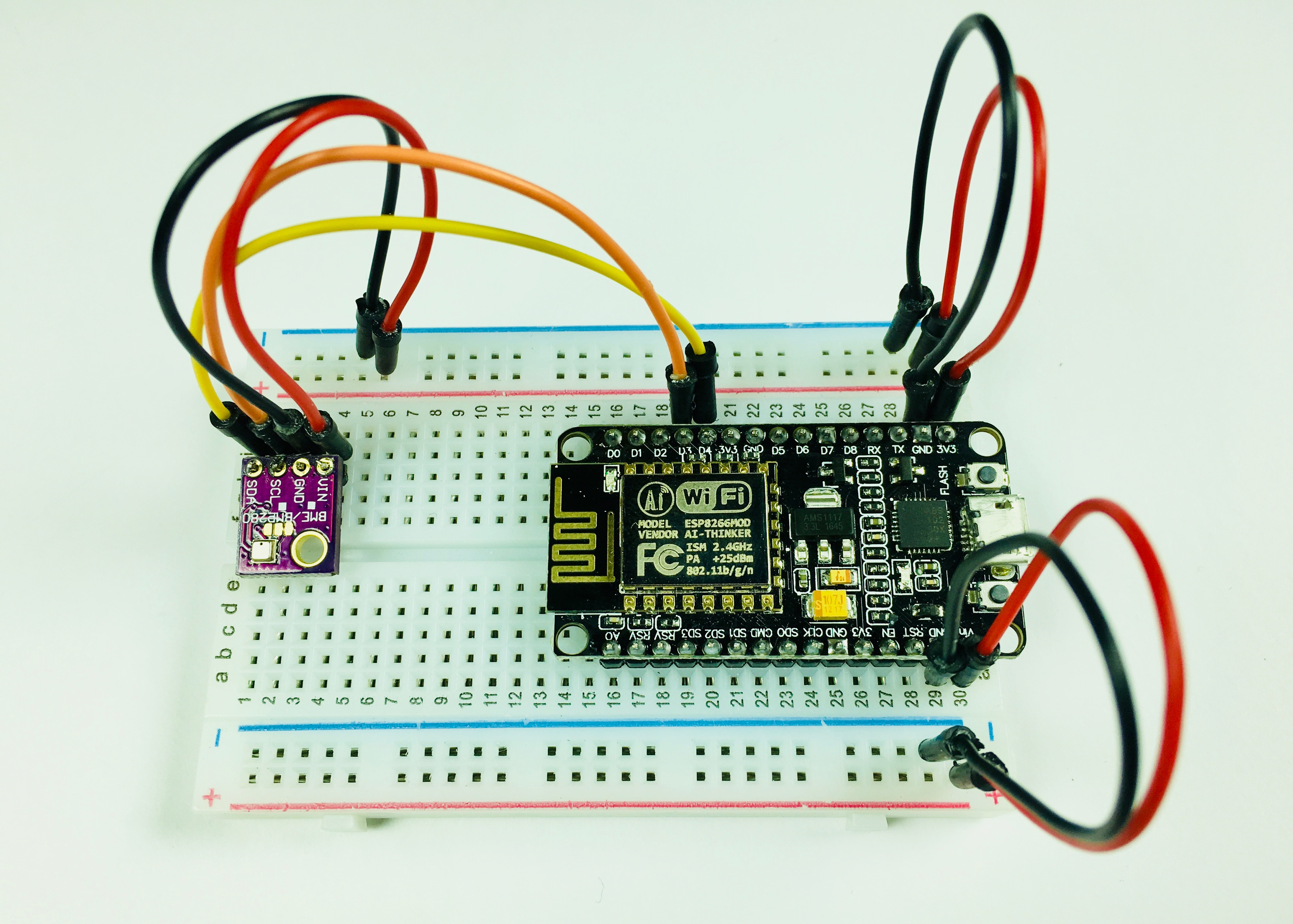
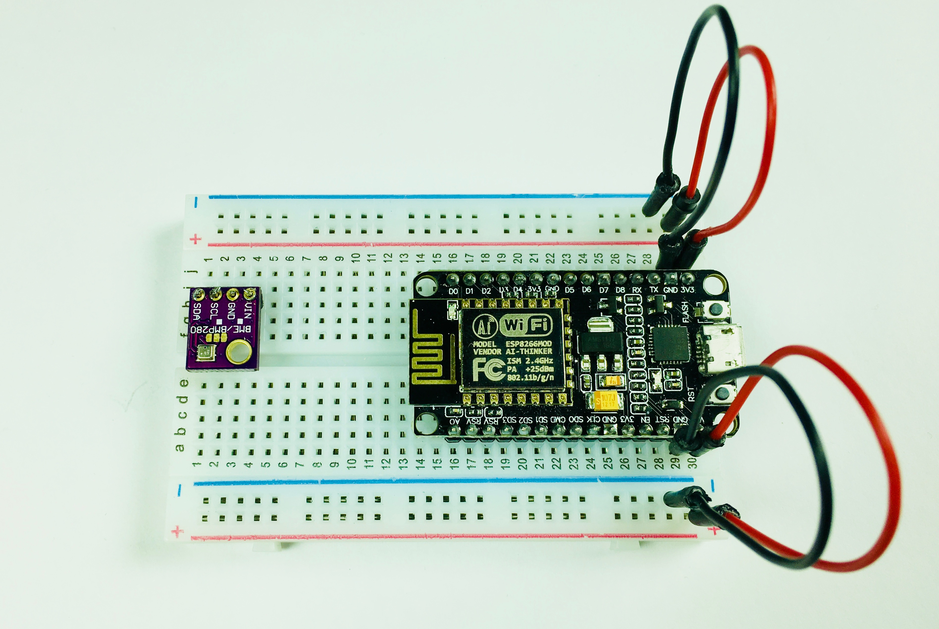
In order to connect the BME280 sensor first, you will need to solder a pin header that arrived with your sensor. Place 4 pin header in 4 holes on your sensor and solder it.
When you are done connect the sensor as shown in the picture above. Use pins H2 to H5.
3.2. Powering BME280

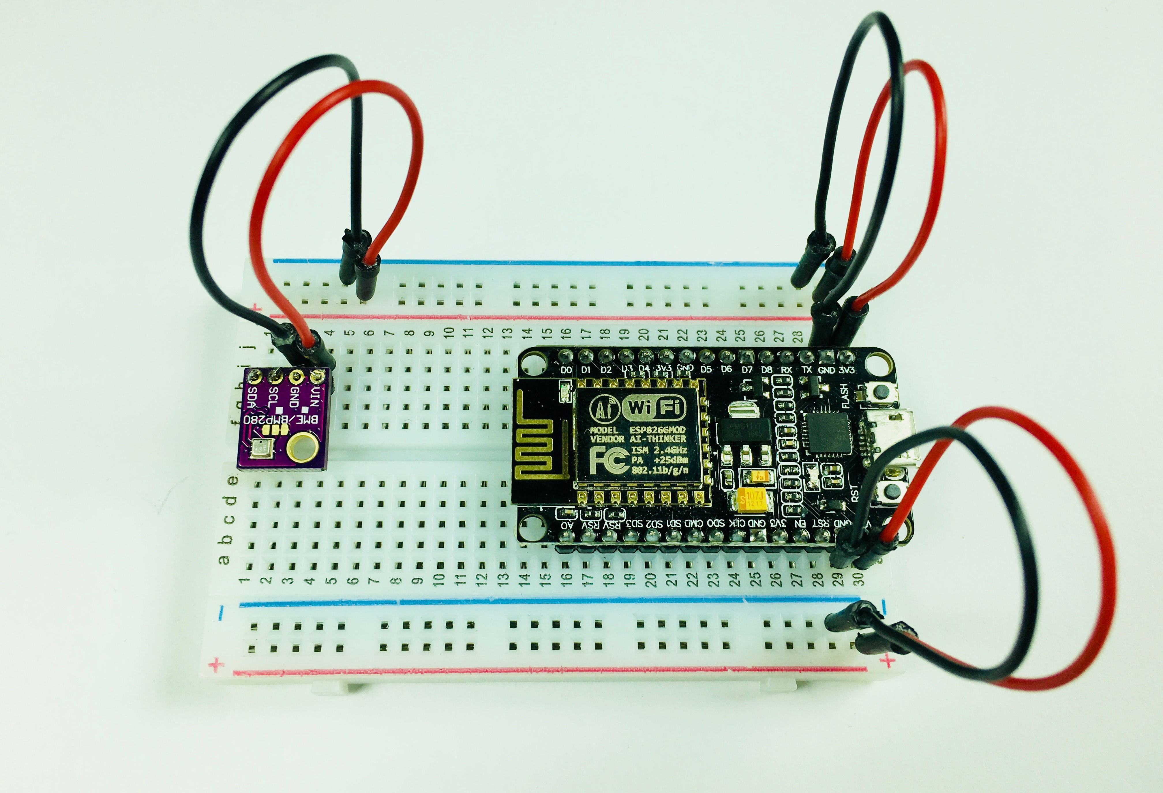
Once you have your BME280 sensor placed on the breadboard, you will also need it powered up and grounded. To do this, use custom, handmade jumper wires previously made on holes I3 and I4 respectively.
Connect hole I4 to Power (column marked with + sign on the right side), and hole I3 to Ground (column marked with a - sign on the right side).
3.3. Connecting it to NodeMCU

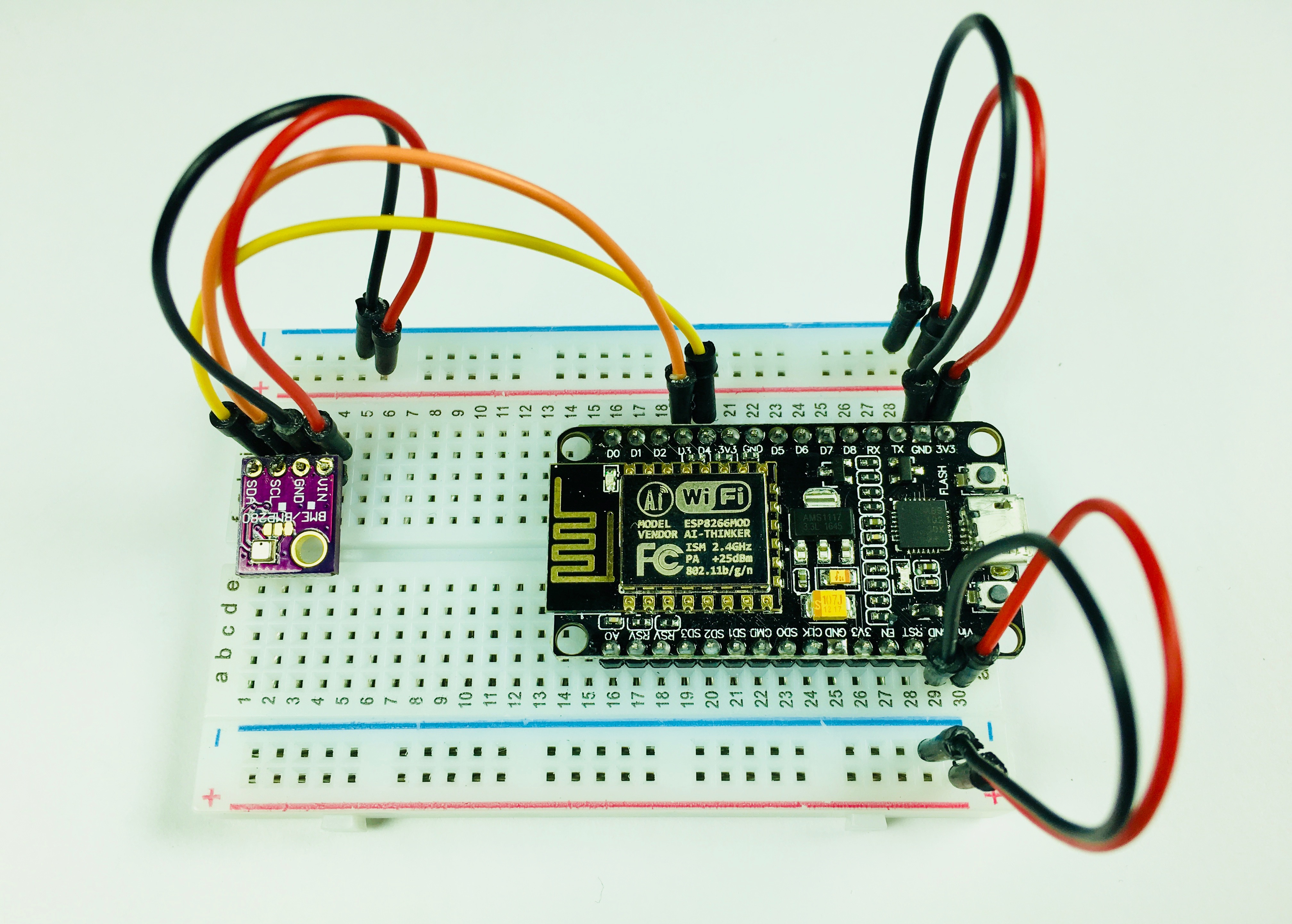
To establish I2C communication you will need to connect the BME280 sensor to NodeMCU.
Use male to male jumper cables to connect:
SCL pin on BME280 (I2) to D3 pin on NodeMCU (J19)
SDA pin on BME280 (I1) to D4 pin on NodeMCU (J20)
When you are done your little setup will look as shown in the picture.
Updated almost 6 years ago
