2. Place PCB
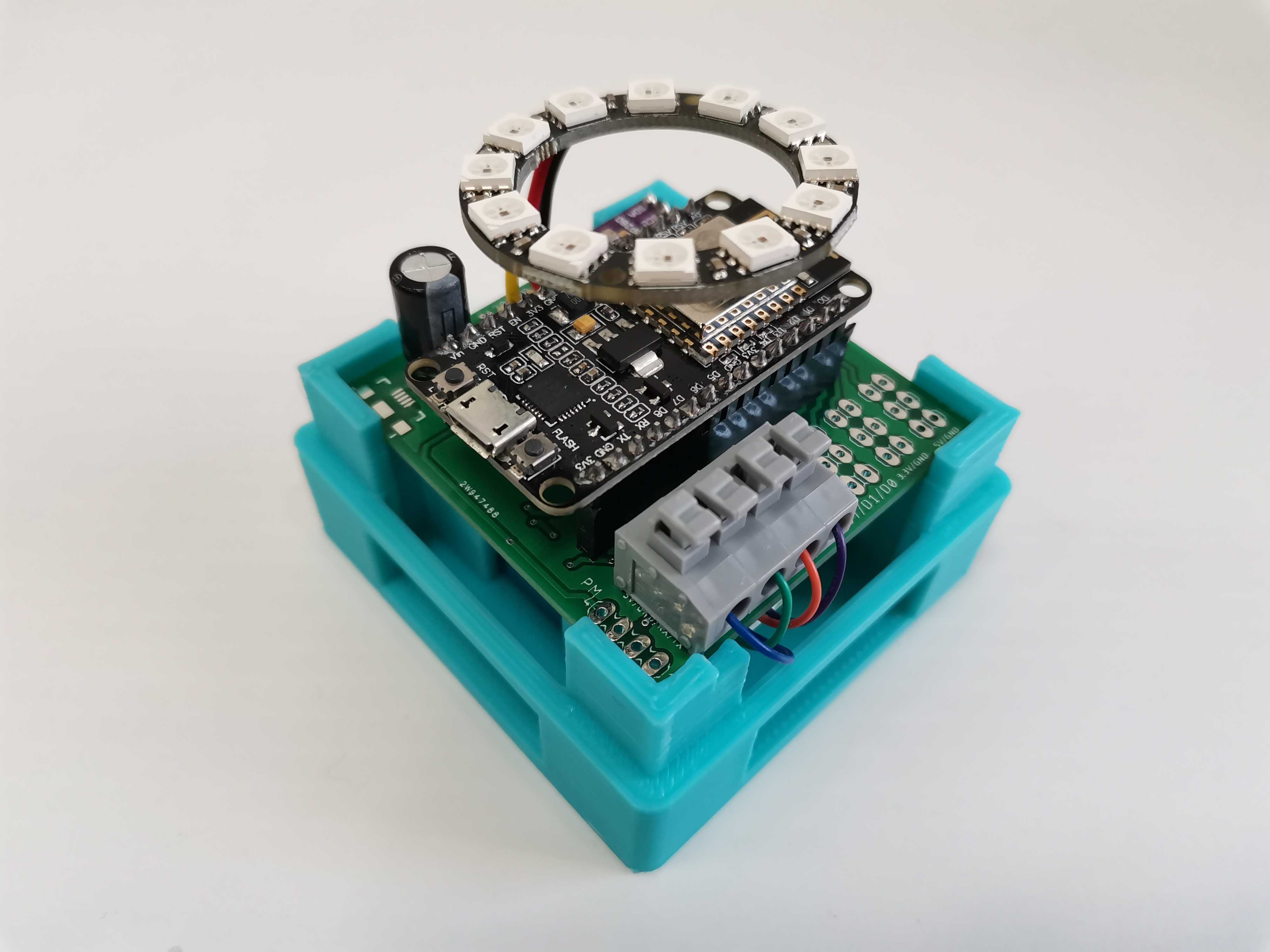
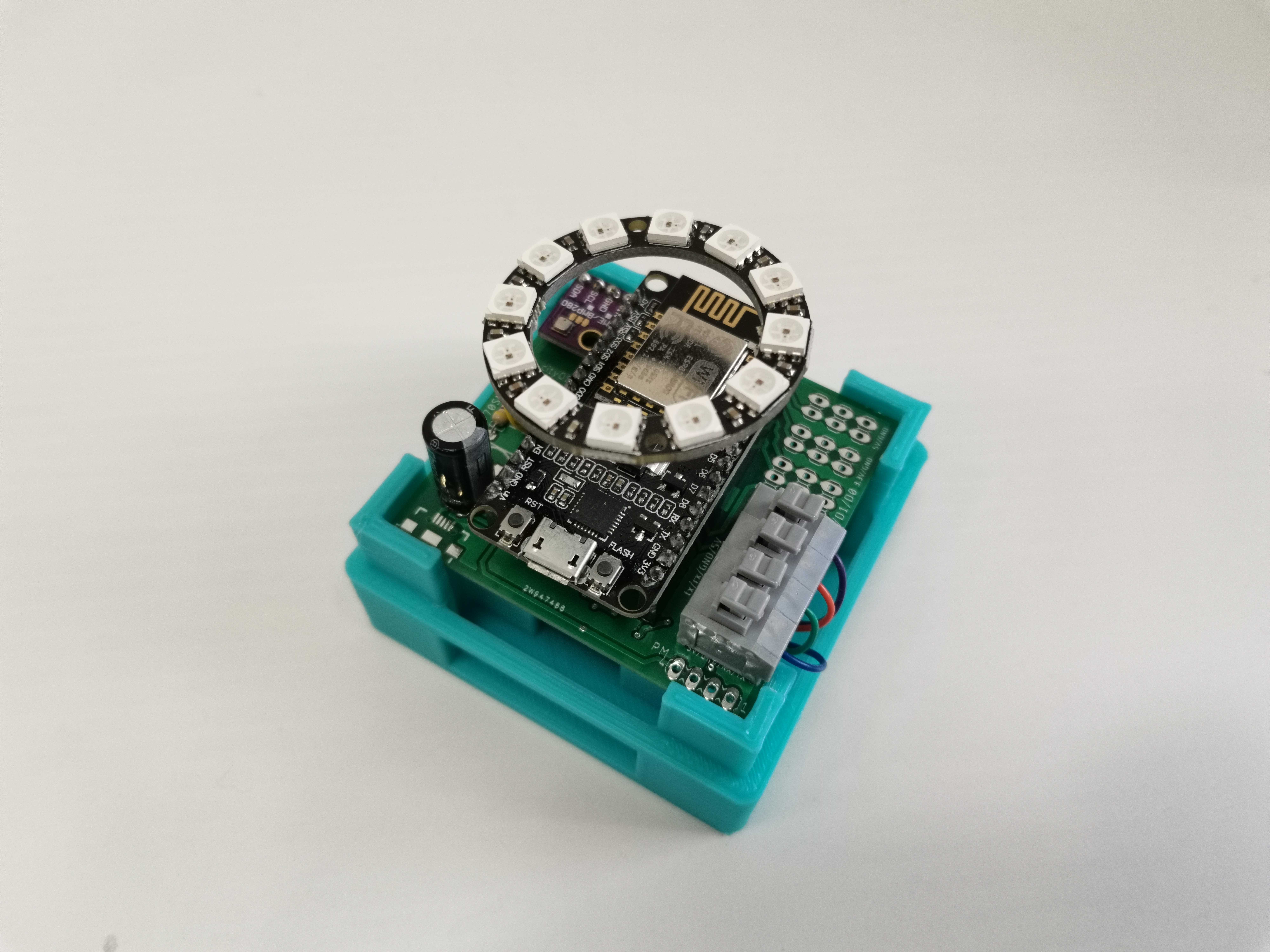
Now that you have connected PM adapter with the PM sensor, it is time to place the PCB inside the housing, as it is shown in the pictures below.
Pay attention, NodeMCU with USB needs to be turned left from the PM adapter.
For PM sensor wiring diagram, please refer to Connect PM Sensor section in PCB assembly instructions.

This is how it should look like when it's done properly.

Updated almost 6 years ago
What’s Next
